Prof. P. A. Christensen
Home
Research and 3rd strand areas
News and recent publications
Vacancies
Information for group members
Clarizon Ltd
Services to business
Updated: 28 Jan 09
|
Electrochemical HydroDeHaolgenation /continued
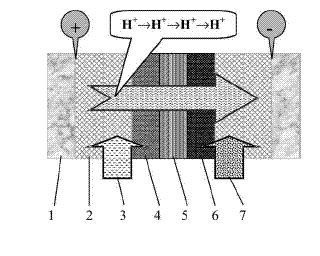
The ZG SPE cell was as follows:

Schematic of the HDH reactor. (1) Stainless steel plate. (2) Stainless
steel mesh. (3) Anolyte (dilute aqueous acidic solution). (4) Pt/Ti mini
mesh anode. (5) Membrane (solid polymer electrolyte). (6) Pd/Ti mini
mesh cathode. (7) Catholyte (halogenated organic compounds + paraffin
oil).
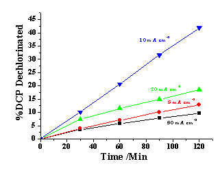
The system chosen to test the cell was 1, 4-dichlorophenol (DCP) in paraffin oil, ie a challenging system for an electrochemical treatment process! Some typical data are shown below:

Effect of current density on the percentage of DCP removal during the electrochemical HDH of DCP in paraffin oil media using a Nafion 117 membrane reactor. Blue 10 mA cm-2; green 20 mA cm-2; red 5 mA cm-2 and black 50 mA cm-2. Cathode: Pd/Ti mini-mesh (20 cm2, 2 mg Pd cm2). Anode: Pt/Ti mini-mesh (20 cm2, 2 mg Pt cm2). Catholyte: 200 mM DCP in paraffin oil (50 cm3). Anolyte: 0.5 M H2SO4 aqueous solution (50 cm3). Flow rate: 50 ml min-1. Temperature: 19 C.

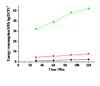
Effect of current density on the energy consumption during the electrochemical HDH of DCP in paraffin oil media using a Nafion 117 membrane reactor. Green 50 mA cm-2; red 20 mA cm-2 and black 10 mA cm-2. The values obtained at 5 mA cm-2 are similar to those at 10 mA cm-2 and thus not be included in the figure for clarity.
As can be seen, the technology works-and works well!
<<Previous.....Home.....Next>>
|


